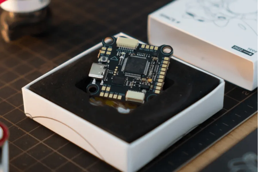
Choosing the right FPV drone flight controller for you requires consideration of the following six factors: processor performance, sensors, compatibility, functionality and scalability, programmability, brand and after-sales service. The processor determines the computing power and responsiveness, sensors are necessary to acquire and process aircraft data, compatibility is needed to ensure hardware and software compatibility, functionality and scalability affect the performance and scalability of the flight control, programmability is very useful for professional pilots and developers, and a well-known brand and good after-sales service can ensure quality and user experience. Make a wise choice according to your needs and budget to better enjoy the fun of flying. Here is specification of MEPS F7 HD flight controller:
| Brand/Product | MEPS SZ F7 HD flight controller |
|---|---|
| Size of flight controller | 30.5mm x 30.5mm |
| MCU | STM32F722RET6 |
| UART Set | 5 |
| IMU | MPU6000 |
| Black Box | 16MB |
| Input Voltage | 3~6S Lipo |
| TVS | 30V |
| BEC | 3.3V/0.5A 5V/3A |
| ESC Agreement | DShot300/600/1200 |
| OSD | Betaflight |
| LED | Betaflight |
Different flight controller sizes
Different sizes of racks need to be matched with different sizes of flight controls, and there are three mainstream sizes:
- Regular size: usually the standard for five-inch machines, but also commonly used in a variety of three-inch crossing machine.
- Mini size: commonly used in racks below three inches, many three inches or five inches of the rack will usually be compatible with mini size flight control
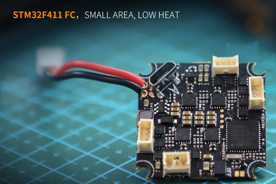
- AIO size: is the abbreviation of All-in-one, meaning that the flight control ESC and even remote receiver all-in-one. Commonly used in the smallest size of indoor traversing machine.
| Flight Control Hole Pitch(mm) | Frame size | Screw sizes |
|---|---|---|
| General:30.5mm | 3″ or more | M2/M3 |
| Mini:25.5mm | 2″ or more | M2/M3 |
| AIO:20mm | Under 2″ / Under 100mm | M1/M2/M3 |
What is the MCU of F4, F7 ?
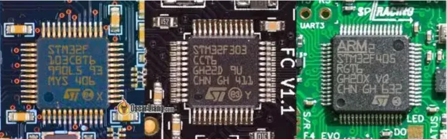
The microprocessor is the key to determine the performance of the flight control, the name of the flight control will generally be directly marked with the model number of F405, F722 and other microprocessors. The model number of the processor can be seen directly on the surface of the chip.

For example, the meanings of the ARM STM32F722 in the above figure are:
ARM: Based on the ARM architecture, it is a commonly used micro-single-chip instruction set.
STM32: 32-bit chip designed by STMicroelectronics (STM).
F722: The model of the chip is F722, which belongs to the F7 series.
The STM32 series chips of the ARM architecture have been developed since 2007, and the technology is very mature. The chips of this series are also updated and iterated year by year, and the F1~F7 series were born. This series is widely used in traversing machines, the specific parameters are as follows:
| MCU) | Freq | UART | Flash | date |
|---|---|---|---|---|
| F103 (STM32F103CBT6) | 72MHz | 2 | 128KB | 2007 |
| F303 (STM32F303CCT6) | 72MHz | 3 | 256KB | 2012 |
| F405 (STM32F405RGT6) | 168MHz | 3~5 | 1MB | 2011 |
| F411 (STM32F411) | 100MHz | 2 | 512KB | 2011 |
| F745 (STM32F745VG) | 216MHz | 5~6 | 1MB | 2014 |
| F722 (STM32F722RE) | 216MHz | 5 | 512KB | 2014 |
| F765 (STM32F765) | 216MHz | 5~6 | 2MB | 2014 |
Taking the common F405 as an example, the meanings of the above parameters are as follows:
- Operation frequency: It is the key to determine the speed of the processor. It directly affects the speed of sampling and calculation of flight attitude. In theory, the faster the better, but 168MHz is basically enough.
- Number of serial ports: connect the maximum number of peripherals that support the UART protocol, and support various external modules such as remote control receivers, GPS modules, and flash memory cards. In theory, the more the better, but the size of the flight controller is limited, and more than five can basically meet the demand.
- Flash memory capacity: Determine the size of the firmware and configuration information allowed to occupy space, the larger the better. With the gradual improvement of Betaflight functions, the space occupied by the firmware is also increasing, and the chips before F3 are gradually being eliminated.
Generally speaking, after the development of the processor to the F4 series, it is no longer the main reason for limiting the performance of the traversing machine. When purchasing, usually choose a processor with higher compatibility and cost performance. For example, although the F745 is better than the F722 in terms of parameters, the latter is cheaper and can fully meet the needs of flight, so most of the current F7 series flight controllers will choose the F722.
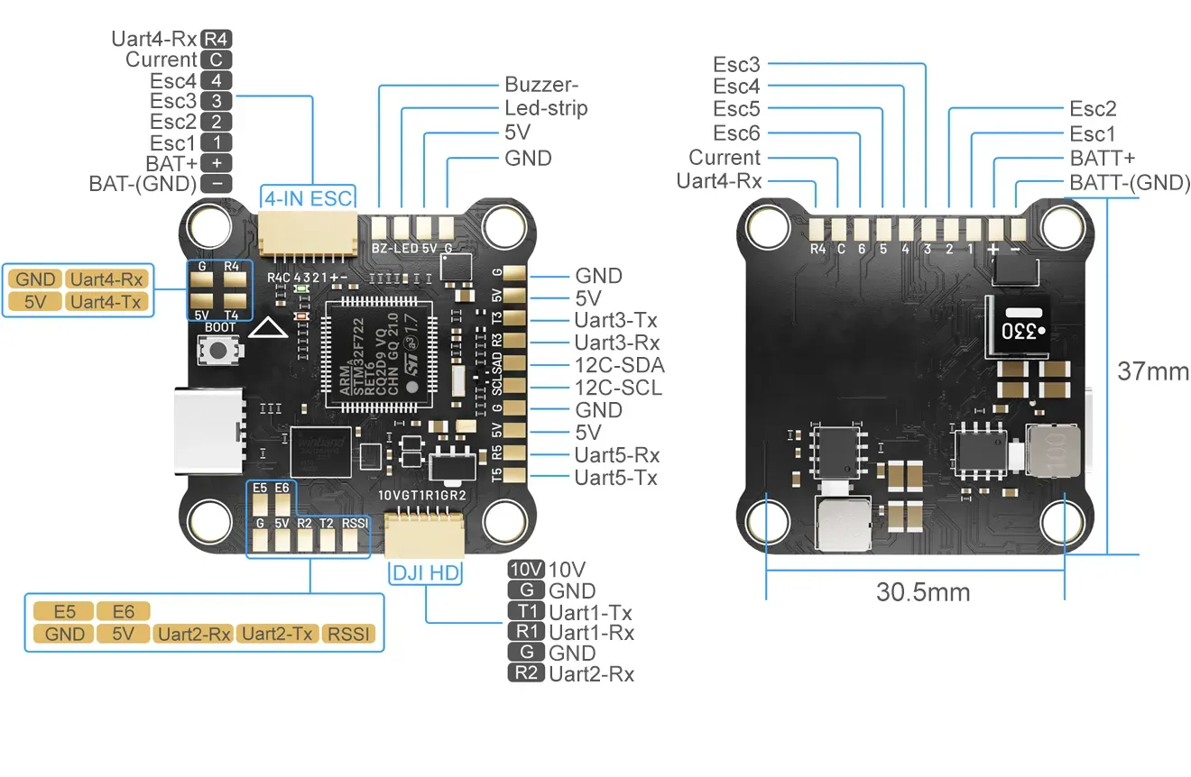
Number of serial ports
The number of serial ports supported by the processor is not always the same as the actual number of serial ports that can be used. On some small flight controllers, only a portion of the serial port is drawn from the chip due to size. In addition, the F7 processor serial port has a signal inverter function, while the F4 does not. Inverters function as follows:
Serial port signal inverter (UART Signal Inverter)
F4 processor does not contain a signal inverter, SBUS must be connected to the RX pin with inverter, so the receiver must be connected according to the connection diagram included with the product. f7 processor has a built-in signal inverter, there is no such problem.
Processor (CPU)
The processor serves as the brain of the flight controller. Flight controller F7 models, such as the Matek F722, offer superior processing power for more complex tasks, making them ideal for racing. However, for standard use, an flight controller F4 like the Omnibus F4 can suffice.
Gyroscope and Accelerometer
Stability and responsiveness depend heavily on high-quality gyroscopes and accelerometers, here is a description of the most commons models.
Gyroscope Models :
BMI270 : The BMI270 is an Inertial Measurement Unit (IMU) developed by Bosch Sensortec. It combines a gyroscope and accelerometer in a compact package, providing accurate motion sensing capabilities. Its high precision makes it suitable for applications where stability and responsiveness are crucial.
ICM42688 : The ICM-42688 is an Inertial Measurement Unit manufactured by TDK InvenSense. It features a 3-axis gyroscope with a wide range of angular rate sensing. Known for its low noise and high sensitivity, the ICM-42688 contributes to precise motion tracking, making it ideal for FPV applications.
MPU6000 : The MPU-6000 is a widely used gyroscope and accelerometer combination produced by InvenSense. It has been a popular choice in fpv plane flight controller due to its reliability and performance. The MPU-6000 offers a range of features, including low power consumption and high sensitivity.
ICM20602 : The ICM-20602 is a triaxial gyroscope produced by TDK InvenSense. Renowned for its high precision and stability, it is a favored choice in the FPV domain. Its performance contributes to precise motion tracking, ideal for responsive flights.
IS2064 : Manufactured by InvenSense, the IS2064 is a digital triaxial gyroscope. With low power consumption and high sensitivity, the IS2064 delivers reliable performance for a variety of FPV applications, ensuring increased accuracy during maneuvers.
Accelerometer Models :
BMI270 : In addition to its gyroscope functionality, the BMI270 also incorporates a high-performance accelerometer. This dual functionality enhances its capability to accurately measure linear motion, making it suitable for applications where both angular and linear motion data are crucial.
ICM42688 : Alongside its gyroscope features, the ICM-42688 includes a 3-axis accelerometer. The accelerometer component provides precise measurements of linear acceleration, complementing the gyroscope data for a comprehensive motion sensing solution.
MPU6000 : The MPU-6000, being an Inertial Measurement Unit, integrates a 3-axis accelerometer along with its gyroscope capabilities. This dual sensor arrangement allows for accurate measurement of both angular and linear accelerations, contributing to stable and responsive drone flight control.
ADXL345 : Analog Devices’ ADXL345 is a popular triaxial accelerometer in FPV. It offers a wide range of acceleration measurement and high resolution, making it a versatile choice for applications requiring accurate linear motion detection.
MPU9250 : InvenSense’s MPU-9250 is an IMU module comprising a triaxial gyroscope and a triaxial accelerometer. Its versatility makes it a favored choice in FPV, providing a comprehensive solution for measuring both angular and linear motions.
These gyroscope and accelerometer models play a crucial role in providing flight controllers with accurate motion data, enabling precise control and stability during FPV flights.
Number of serial ports
The number of serial ports supported by the processor is not always the same as the actual number of serial ports that can be used. On some small flight controllers, only a portion of the serial port is drawn from the chip due to size. In addition, the F7 processor serial port has a signal inverter function, while the F4 does not. Inverters function as follows:
Serial port signal inverter (UART Signal Inverter)
F4 processor does not contain a signal inverter, SBUS must be connected to the RX pin with inverter, so the receiver must be connected according to the connection diagram included with the product. f7 processor has a built-in signal inverter, there is no such problem.
IMU Sensor
The attitude sensor is a micro sensor chip based on micro-electromechanical system (MEMS). The common attitude sensor models include MPU6000, MPU6050, etc., which are connected to the processor through the SPI bus to detect the attitude of the traversing machine.
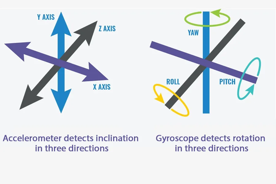
The attitude sensor usually integrates an acceleration sensor (Accelerometer) and a gyroscope (Gyroscope), and the functions are as follows:
- Acceleration sensor (Gyro): Detect the space tilt attitude of the traversing machine in three directions.
- Gyroscope (Acc): Detect the rotation speed of the traversing machine in three directions.
In addition, there are also sensors such as MPU6050 integrated with an electronic compass, which can be used to sense geographic directions. However, there are many electromagnetic devices on the traversing plane, and the electronic compass generally needs to be calibrated before it can be used.
MEMS sensors require strong physical and electronic anti-noise capabilities. MPU6000 is relatively excellent in both anti-noise indicators and is currently the most commonly used model.
- Physical anti-noise: It means that the traversing machine can still detect the attitude stably during the variable speed movement. The glue on the flight control studs can effectively reduce physical noise.
- Electronic noise resistance: refers to the ability to accurately output signals in circuit fluctuations. A flight controller with better performance usually uses a low dropout regulator circuit (Low Dropout Regulator) to isolate power supply for the sensor.
In addition, the sampling rate is another important indicator of the sensor. In theory, the higher the sampling rate, the better, but due to interference from circuit fluctuations, too high a sampling rate often has no effect. The 8KHz of the MPU6000 is a relatively compromised choice. The sampling rate in BF is this meaning
Black Box Flash
The flash memory in the processor is limited and can only be used to store firmware and parameters, so a flash memory chip is generally integrated on the flight controller to store flight data. At present, the size of flash memory generally ranges from a few megabytes (MB) to tens of megabytes, and can generally store tens of minutes of flight data.
Input Voltage
The input voltage refers to the voltage range of the flight control power supply. The power supply of the flight controller is divided into two types: ESC power supply and lithium battery power supply. The 3~6S Lipo (12.6~25.2V) in the typical parameter table means that the flight controller can be directly plugged into a 3~6S lithium battery, or connected to a 12.6~25.2V ESC for power supply. However, it is not ruled out that some flight controllers cannot be directly powered by lithium batteries. If the voltage is too high, it may cause the flight controller to burn out. When choosing and matching, you need to pay attention to the voltage range.
Output Voltage (BEC)
The on-board step-down circuit (Battery Eliminate Circuit) on the flight controller can reduce the input voltage to several levels to supply power to various components. The most conventional output voltages are 3.3V, 5V, 9V, etc. The uses can be divided into model voltage and driving voltage.
Signal voltage: usually 3.3V and 5V, used to power peripherals such as the remote control signal receiver of the traversing machine. Most of these components are used to send and receive signals, and the current is small.
Driving voltage: usually 5V and 9V, used to drive high-current devices, such as FPV cameras, image transmission, LED lights, etc.
When connecting devices, pay attention to whether the output voltage is within the rated range of the external components, and whether the current of the external devices is less than the maximum current of the BEC.
ESC protocol
DShot (Digital Shot) is currently the most mainstream digital ESC protocol for traversing aircraft. Compared with the traditional analog ESC protocol, DShot has stronger anti-interference ability. The number after DShot represents the frequency of data transmission. For example, the most common DShot600 represents the communication rate between the flight controller and the ESC is 600,000 bytes/second. Since the frequency of DShot is far beyond the perception range of most flight controllers, just pay attention to whether the protocol of the flight controller is compatible with the ESC.
OSD
The OSD chip is used to superimpose more information on the image signal captured by the camera. The early flight control software and hardware functions were not perfect, and the OSD module needed to be purchased additionally and manually soldered to the flight control. At present, the OSD chip is basically the standard configuration of the flight control.
LED
The flight controller of the traversing plane supports the connection of WS2812 series three-color (RGB) LED strips. In Betaflight, you can individually set the lighting effect for each lamp bead on the light strip. In addition, we can also set simple trigger conditions for these lights, such as increasing the throttle to show green, and showing red when the battery is too low.
The LED signal port on the flight controller determines the number of light strips that can be independently controlled. Several lamp beads can be connected in series on each light strip. When purchasing a flight controller, you need to pay attention to the 5V output current of the BED. A single lamp bead needs to be driven by a current of more than 0.3A.
Different Types of Flight Controllers
FPV Drone Racing Flight Controller
FPV racing demands minimal latency. FPV racing flight controller like the Hobbywing XRotor F7 ensure maximum responsiveness, providing a crucial advantage in competitive racing.
When choosing the best racing flight controller, responsiveness and low latency are a significant criteria. Lighter and more compact flight controllers are often preferred for fast and agile racing. F4 or F7 flight controller models may be suitable depending on the complexity of maneuvers.

Freestyle FPV Flight Controllers
Doing tricks in the sky requires a combination of power and stability, that’s the difference between the characteristics of a freestyle and racing quad flight controller.The MEPS SZ F7 HD offers a perfect balance, allowing pilots to execute complex maneuvers with exceptional responsiveness. For freestyle flying, where the fluidity of movements is crucial, a flight controller offering a combination of high processing power and stability is preferable. Flight controller F4 and flight controller F7 models can also be balanced choices, depending on the individual preferences of the pilot.
Cinematic FPV Flight Controllers
Cinematic flying requires absolute stability for smooth footage. Controllers like the Aikon Mini F7 flight controller ensure increased stability, creating an ideal environment for cinematic aerial captures. Regarding FPV cinema and television drones, « Heavy-lift FPV drones », with them 8 motors, will require a specific flight controller capable of handling this configuration. Drone flight controllers designed for multi-motor setups must provide excellent motor management, increased stability, and compatibility with camera control systems necessary for cinematic production.
How to Choose the Function of the FPV Flight Control ?
The Factors You Need to Consider When Choosing Flight Controller Functions
- Flight Purpose: You must select a flight controller that supports FPV, aerial photography and automatic return functions if it is to be used for aerial photography. You must select a flight controller with low voltage protection, overshoot control and obstacle avoidance functions if it is to be used for racing.
- Budget: The price of a speed controller increases with the number of functions.
- Personal preference: Some features, such as automatic take-off and landing, are not necessary but can enhance the flying experience.
The following are detailed explanations of the functions of flight controllers:
- Basic functions: These include attitude control, position control, speed control, and motor control. These are necessary features for every flight controller. These features guarantee that the drone stays in a steady flight position and follows instructions.
- Functions for aerial photography: These can be used with drones and include FPV, aerial photography, intelligent follow, and automatic return.
- Drone racing can benefit from these features, which include obstacle avoidance, overshoot control, and low voltage protection. We should also take into account the flying control’s lightweight design and lack of a high-definition interface.
- Additional features: These consist of self-stabilization mode, automated takeoff, and aided landing, which can be chosen based on various requirements.
It is necessary to configure the automated air return feature and take into account flight control using the GPS interface.
The following flight controller features are crucial for novice pilots:
- Fundamental features: These features, which include motor control, attitude control, position control, and speed control, are necessary for all flight controllers. These features guarantee that the drone stays in a steady flight position and follows instructions.
- Self-stabilization mode: In the event that the pilot loses control, this mode assists the drone in keeping a steady flight attitude. This can help keep the drone from crashing, which makes it especially crucial for inexperienced pilots.
- Low-voltage protection: When the drone’s battery is running low, this feature keeps it from losing control. All pilots should be aware of this, but novices should be especially mindful of it since they might not know how much battery life the drone has left.
Beginning pilots might also wish to think about selecting a flight controller that has the following qualities in addition to these crucial ones:
- Helped landing: This function makes it easier for the pilot to bring the drone down. This might lessen the chance of a drone crash during landing, which can be beneficial for inexperienced pilots.
- Without the pilot’s input, the drone lifts off autonomously thanks to this capability. This might lessen the chance of the drone crashing during takeoff, which can be beneficial for inexperienced pilots.